How to laser-cut a 1:500 site model from contours
A stacked contour model is the quickest way to make a site legible: one layer of board per contour step. This guide covers the whole method. You can follow it with our free Bath sample pack, or with contours you have drawn yourself.
The worked example is the free Royal Crescent, Bath pack: a 250 × 175 m site at 1:500 on 3 mm board, which gives 9 layers on 7 boards of 600 × 400 mm.
1. Match the contour step to the board
This is the one rule that makes the model true to scale: the contour interval must equal the board thickness at model scale.
interval on site = board thickness × scale
| Board | 1:500 | 1:1000 |
|---|---|---|
| 1.5 mm | 0.75 m | 1.5 m |
| 2 mm | 1 m | 2 m |
| 3 mm | 1.5 m | 3 m |
If your contours are at 1 m and your board is 3 mm, a 1:500 model will be twice as steep as the real site. Either change the board or regenerate the contours. In the Bath pack the interval is 1.5 m, because 3 mm × 500 = 1.5 m.
2. Work out the size and the number of layers
Model size is site size divided by the scale: 250 × 175 m at 1:500 is 500 × 350 mm, which fits one 600 × 400 mm board. The number of layers is the height difference across the site divided by the interval, plus the base. Bath runs from 40.6 m to 53 m, about 12.5 m of relief, so 9 layers at 1.5 m.
Count the board before you start. On a gentle site most layers are nearly as big as the base, so each needs a board of its own: the Bath model takes 7 boards for 9 layers. Steeper sites nest better because the upper layers are narrow strips.
3. Make every layer a closed outline
A contour line that runs off the edge of the site cannot be cut. Each layer has to be a closed shape: the contour, closed along the site boundary, enclosing everything at or above that height. Layer 0 is the whole site (the base). Layer 1 is everything above the first contour, and so on.
If you are doing this by hand in Rhino or AutoCAD: draw the site rectangle, trim each contour to it, then join each contour with the part of the rectangle on its uphill side. Check every outline is closed before you export; an open curve will engrave, not cut.
4. Remove what the laser cannot cut
Anything narrower than about 3 mm will burn away or snap. Delete thin slivers and tiny islands, and let that area stay part of the layer below. Smooth out wiggles smaller than a few millimetres: they add cutting time and char without adding information.
5. Add registration: number each piece and mark where the next one sits
Nine similar-looking layers are easy to mix up. Engrave a number on every piece, and engrave the outline of the layer above onto each layer. That outline is your glue line: you place the next piece exactly on it, with no measuring.
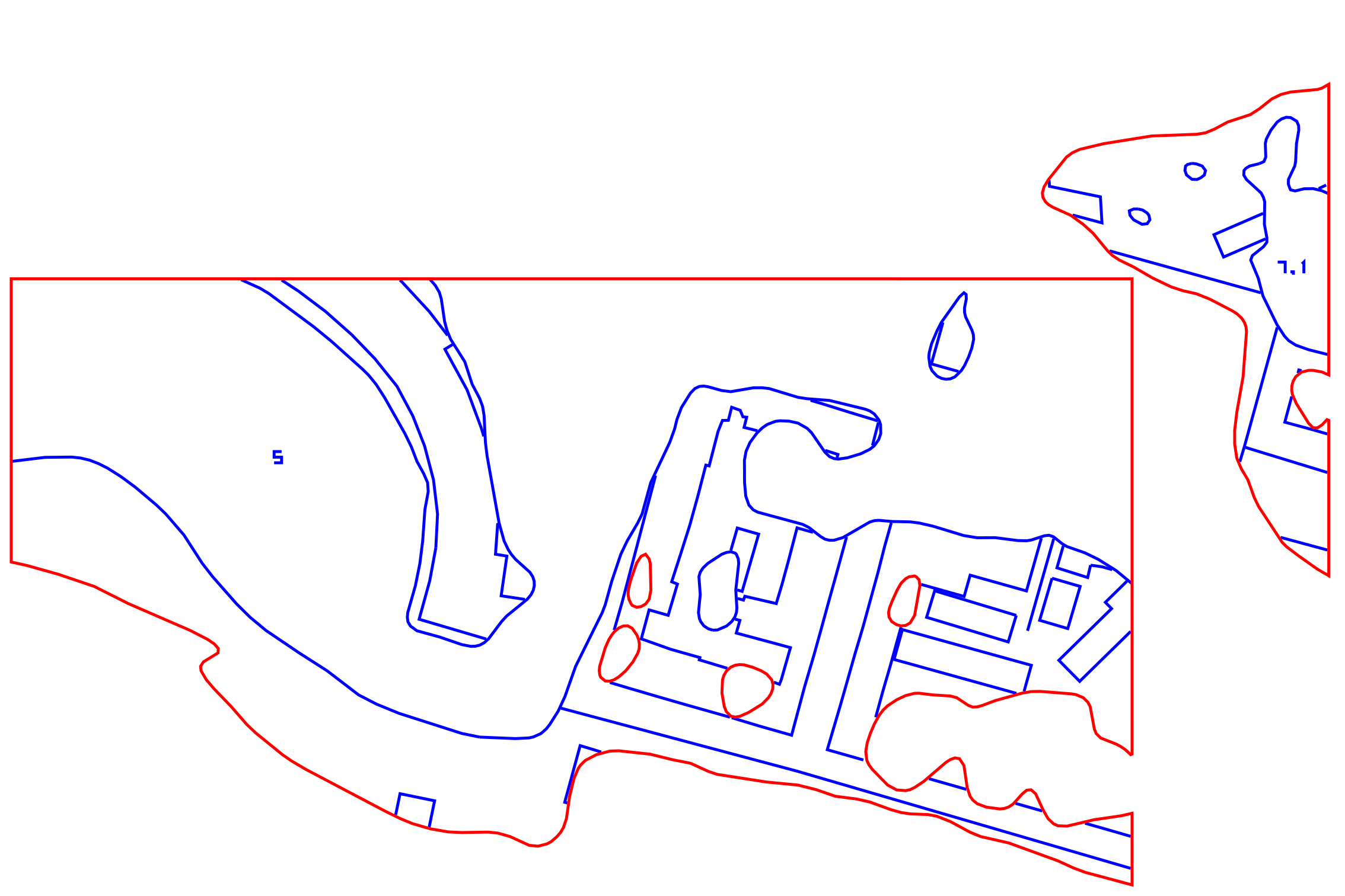
6. Lay the pieces out on boards
Keep at least 5 mm from the board edge and 3 mm between pieces. Put small pieces in the offcuts beside large ones. Use your lab's colour convention; the most common is a red hairline to cut and a blue hairline to engrave, in RGB, at the thinnest line weight your software allows. Ask your technician if you are not sure, because a wrong colour is usually ignored silently.
The sheets in the pack are already laid out this way, as DXF and SVG in millimetres. Each DXF also has a layer called BOARD_OUTLINE_DO_NOT_CUT: hide or delete it before sending the job.
7. Cut
- Use the settings your lab publishes for your material and thickness, and test them on an offcut first. Settings differ between machines, so numbers from the internet are not reliable.
- Run the engraving before the cutting, so pieces do not shift once they are free.
- Check the board lies flat. Warped card goes out of focus and does not cut through.
- Greyboard, mountboard, MDF and plywood all work. Corrugated card is cheap but its real thickness varies, so measure it.
- Collect pieces sheet by sheet and keep them in number order.
8. Glue up
Start with layer 0. Glue layer 1 onto its engraved outline, then layer 2, and work upwards. PVA spread thinly is enough; weight the stack with books while it sets so the layers do not curl. Where a layer has several pieces they are numbered 3.1, 3.2 and so on, and each has its own outline on the layer below.
The Bath pack is a solid stack: every layer is a full piece, which is sturdy and simple. To save board on a large model you can hollow the hidden middle of each layer, leaving a rim of 10 to 15 mm for glue.
9. Buildings
The footprints engraved on the steps show where buildings go. Cut blocks from foam or card, or extrude them from the CAD file: in the pack, contours.dxf and site.3dm hold each building with its height.
What accuracy to expect
Open LiDAR terrain is accurate to roughly ±15 cm vertically on open ground, less under trees and beside buildings. At 1:500 that is well under the thickness of the board. Building outlines and heights from open data are indicative. This is a desk study for design and model-making, not a survey.
Try it
Courbia is not on sale yet. The sample packs are free and need no email.
